Hydrogen Ambassadors International
Competition
Online Vote has completed:
All Hydrogen Ambassador Teams have won!
 |
Meet
Our Winners!
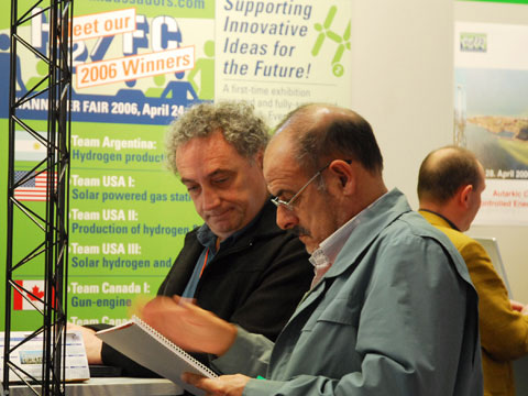
Congratulations to the winning teams of the
2006 Hydrogen Ambassadors Competition
fully sponsored by Arno A. Evers and the
FAIR-PR Team! |
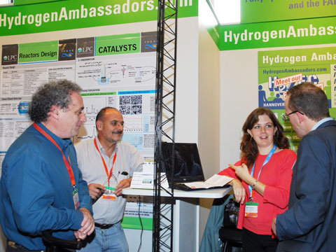
Team Argentina:
Hydrogen production from bio ethanol
Booth Number:
H78/5
 |
Miguel Angel Laborde (57)
Pio Aguirre (48)
Betina Schönbrod (26)
University of Buenos Aires, Department of Chemical Engineering
Buenos Aires, Argentina |
| |
|
|
Miguel Angel Laborde |
Pio Aguirre |

Betina Schönbrod |
Hydrogen catalytic production and purification from bioethanol
Laboratorio de Procesos Catalíticos
Facultad de Ingeniería
Universidad de Buenos Aires
Pabellón de Industrias, Ciudad Universitaria, 1428
Buenos Aires
Argentina
INGAR, Instituto de Ingeniería y Diseño (CONICET-UTN)
Avellaneda 3657, 3000 Santa Fe
Argentina
Correspondence to: Miguel A. Laborde
TE/FAX: 54-11-45763240/1
e-mail: miguel@di.fcen.uba.ar
The Catalytic Processes Laboratory (LPC) and the Design and Development Institute (INGAR) developed a smart system that transform bioethanol to synthesis gas for chemical industries and clean hydrogen for different types of fuel cells including MCFC, SOFC, PAFC, PEFC.
|
Introduction
There exist several routes for hydrogen production from primary
fuels. The clean and non-contaminant feature of H2 as a fuel
will depend on the process and raw material employed for its
production as well as the source of energy required for this
process. If it is obtained from hydrocarbons, carbon oxides
are generated regardless the technology used; thus, the quality
of clean fuel is only true when the raw material is biomass,
which consumes CO2 during its production (growth). Ethanol
is a renewable, non-toxic and easy to manipulate source, and
has therefore excellent chances to replace fossil fuels.
The new application of H2 as a raw material for fuel cells
for mobile sources (PEM) requires that the anode inlet gas
has a CO concentration lower than 10 20 ppm. Otherwise, the
anode is poisoned and the cell efficiency abruptly drops.
Hence, if H2 is produced from hydrocarbons or alcohols, purification
is required in order to reduce the CO levels to fuel cell
requirements.
The Catalytic Processes Laboratory, in cooperation with
INGAR, both from Argentina, has developed a catalytic system
to produce fuel grade green H2.
Process
The system developed in Argentina consists of three catalytic
reactors connected in series and operating at atmospheric
pressure, as it can be seen in Figure 1.
Figure 1. Reactors scheme
The first reactor, the ethanol steam reformer, contains
a nickel based catalyst; it is fed with a mixture of ethanol
and water, previously vaporized. Considering that the reaction
is endothermic, the reactor must be heated and energy is consumed.
Working at temperatures lower than 700ºC, the feed is
converted to a gaseous mixture containing hydrogen, carbon
monoxide, carbon dioxide and methane. A dry gas mean composition
of this mixture, is: H2 70%, CO: 8.6%, CO2: 15.7%, CH4: 5.4%.
It must be noted that this mixture can be used in chemical
and petrochemical industries to obtain different chemicals
products that nowadays are obtained from oil.
A purification of this effluent is required in order to
reduce the CO levels to PEM fuel-cell requirements. So far,
the most technologically feasible purification sequence consists
of a water gas shift converter (WGS) and a latter step to
eliminate or reduce the remaining CO by selective or preferential
oxidation (COPROX).
In the water-gas shift reactor, containing a copper based
catalyst and operating at temperatures lower than 250ºC,
CO concentration is reduced at 2% producing additional H2.
A typical dry gas composition of the effluent is: H2: 76.4%,
CO: 1.2%; CO2: 17.4% and CH4: 5%. As this reaction is slightly
exothermic, an adiabatic reactor can be used. The WGS reactor
is expected to have the largest volume, since this reactor
operates close to equilibrium conditions. The effluent can
be used to feed the high temperature fuel-cells (solid oxide,
phosphoric acid and molten carbonate) without further treatments.
In the COPROX reactor, the WGSR effluent is mixed with air
(or O2) and CO remaining is oxidized to CO2. In this reactor
the oxidation of H2 also occurs. Then a highly selective catalyst
must be employed in order to reduce the hydrogen oxidation
as much as possible. The COPROX reactor operates with a CuO-CeO2
catalyst at temperatures lower than 250ºC. As both reactions
as highly exothermic, a temperature control must be performed.
At the outlet of this reactor CO concentration must be lower
than 20 ppm.
Process synthesis and design tasks of fuel processor were
made applying process integration techniques, to achieve a
satisfactory global efficiency of the system.
Heat exchanged between the reformer outlet streams, hot
streams and the feed cold stream should be maximized. Higher
reformer temperatures diminish the processor efficiencies.
Water-to-fuel ratio fed to the reformer is a critical decision
variable. Water excess must be evaporated and re-heated consuming
additional fuel in the reformer. Shaft power is necessary
in air compression to feed fuel cell system. It can be supplied
by expanding the post combustion gases in an expander within
the integrated system.
Units to be installed in vehicles require specific designs
for small size process units.
A model-based reactor optimization permits to obtain optimal
design.
Modeling the combustion chamber coupled to the reformer
allowed optimizing the design variables to reduce the equipment
volume (0.04 L/kW).
The WGS reactor unit (0.62 L/kW) has the largest volume.
The heterogeneous model used allows computing the optimal
reactor length and diameter and the optimal catalyst particle
diameter.
The COPROX (0.02 L/kW) reactor requires catalysts with high
CO selectivity to reduce the oxidation of H2.
Maximum efficiency, and minimum operation and investments
cost in the entire system are required. Proper integration
among heat and power sinks and sources must include the fuel
processor and the cell.
Considering fuel processor for 1kW fuel cell, the main energy
consumers are the reformer feed heating-evaporating-reheating
(0.72 kW ), the endothermic reformer reaction (0.37 kW), the
compression of air to feed reformer heater, COPROX and the
cell (0,16 kW), and the cell cooling system which involve
a water radiator with a fan cooler .
The reformer reactor heat must be supplied by burning external
fuel and the anode outlet stream that contain a hydrogen fraction
close to 30% (dry base) due to partial utilization in the
cell. Less hydrogen flow from the anode stream implies more
additional fuel to compensate the energy needs. Figure 2 shows
the process integration.
A fraction of the cathode outlet stream can be added as
oxygen source to the air combustion in the reformer section.
Less oxygen utilization in the cell require more air (oxygen)
to be blow, and more energy used. Summarizing: new catalitic
systems and a new integrated process were developed achieving
stable operation and high efficiencies.
|